03. Sampling Analog Signals
Sampling Heading
Digital Sampling
ND320 C4 L1 03 Sampling Analog Signals
Sampling Analog signals Recap
Summary
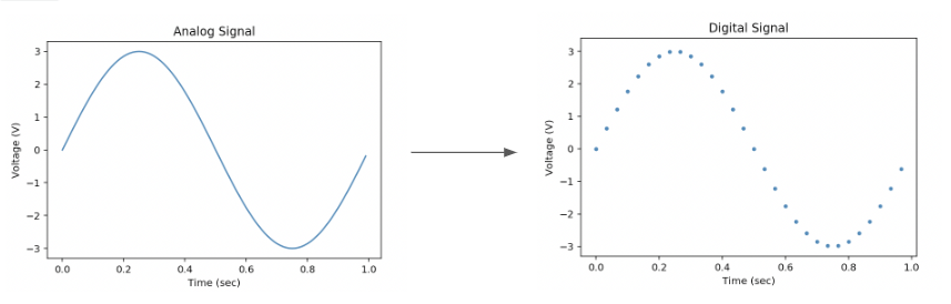
The goal of digital sampling is to take an analog continuous-time signal, typically a voltage, and to quantize it and discretize it in time so that we can store it in a finite amount of memory and use the magic of computers to process it. The component that does this is called an analog-to-digital converter or an ADC, this is an example of a **transducer, you will learn more about transducers in a future lesson. It is important to learn about the few fundamental ways the ADC changes the analog signal. In our head, it’s easy sometimes to pretend that we’re dealing with an ideal analog signal, but this can get us into trouble, and it’s important to know more detail about how signals are sampled to avoid pitfalls later on.
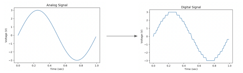
An ADC encodes a range of physical values to a set of discrete numbers. In this example, the analog signal varies over time between -3V and +3V and we are using a 4-bit ADC, which means that the ADC has 4 bits to encode the range from -3 to +3 (ie. the bit-depth of our sensor is 4). The 4 bits indicate that there are 16 discrete values and we can see the effect of this quantization in the digitized signal.
Quantization Noise
Quantization Noise
quant to noise floor
But typically, ADCs have many more bits and you won’t see quantization noise because it will be overpowered by other noise sources.
- Latent thermal energy in the system.
- Electronic noise from within the sensor.
- Electronic noise from the surroundings and the building itself.
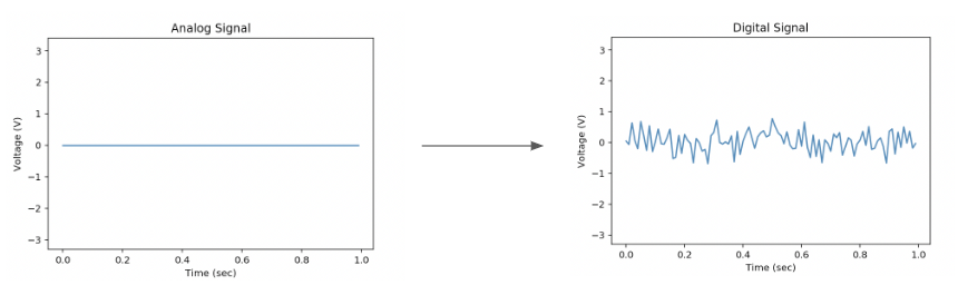
All these types of noise contribute to what we call the noise floor. Even when the incoming signal is perfectly flat, you will see some noise in the output. If you ever see a flat line at 0 in the output, it’s because your sensor is broken.
Noise Floor
Noise Floor
Additive Noise
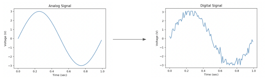
This noise is additive, so you’ll see it on top of whatever incoming signal you have.
Additive Noise
Additive Noise
Signal Clipping
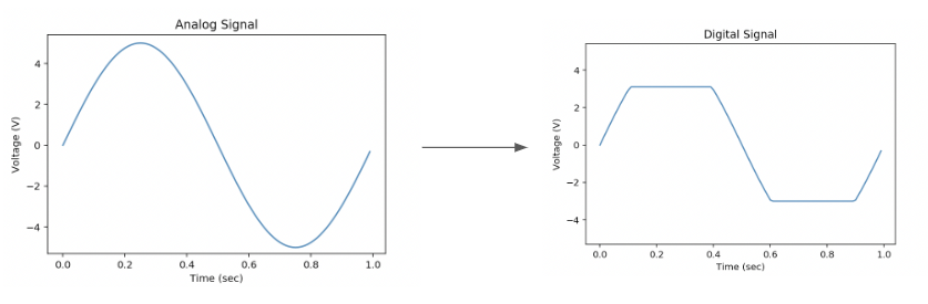
ADCs have a fixed range on the input. So for this example, our ADC was limited to -3V and +3V. This is known as the dynamic range of our sensor. When the input signal exceeds the dynamic range of the sensor, in this case from -4 to +4, everything greater than 3 will be clipped and set to 3 and everything smaller than -3 will be clipped to -3. We call this effect clipping, oversaturation, or undersaturation.
Signal Clipping
Signal Clipping
Sampling Rate
And finally, it’s important to remember that digital signals are sampled periodically in time. We often plot them as these continuous signals by connecting the dots in between, but they are better represented as a sequence of individual points. In this example, there are 30 samples in this second, so we would say the sampling rate is 30 samples per second or 30 Hz.
Sampling Rate
Sampling Rate
Given sampling rate, what is the distance between two successive samples in milliseconds
SOLUTION:
8Two Data Streams
QUIZ QUESTION::
Below are two signals represented in a table with their timestamps and the signal value. Match the signals with their sampling rates.
ANSWER CHOICES:
|
Signal Value Tables |
Sampling Rate |
||||||||
|---|---|---|---|---|---|---|---|---|---|
|
|||||||||
|
SOLUTION:
|
Signal Value Tables |
Sampling Rate |
||||||||
|---|---|---|---|---|---|---|---|---|---|
|
|||||||||
|
Glossary
New Vocabulary
- Transducer: Part of a sensor that converts a physical phenomenon into an electrical one (e.g., voltage)
- Analog-to-Digital Convert (ADC): A device (usually embedded in the sensor) that converts an analog voltage into an array of bits.
- Bit depth: The number of bits an ADC uses to create a sample. A 16-bit ADC produces a 16-bit number for each sample.
- Noise floor: The total amount of noise in the sensor, including electrical interference from the environment and other parts of the device, thermal noise, and quantization noise.
- Dynamic range: The physical range of the sensor. Values outside of this range will show up as clipping in the digital signal.
- Sampling rate: The frequency at which a sensor measures a signal.
Sampling Further Research
Further Research
- Sampling Signal Processing Wikipedia